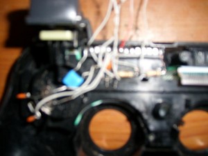
Purtroppo l’idea di un PSGroove su Sixaxis non si è rivelata quello che speravamo. In realtà gli sviluppatori sono realmente riusciti a creare un controller Sixaxis in grado di jailbreakkare la nostra amata PS3, ma non nel modo sperato. Infatti l’idea si basa solamente sull’introduzione di una PIC 18F2550 all’interno del joypad.
Sinceramente non mi sembra che questa idea sia molto intelligente. Fare saldature su un joypad da più di quaranta euro, rischiando di romperlo, non è a mio parere molto intelligente. Ho postato questa notizia solo per calmare gli animi di tutti coloro che pensavano di poter flashiare il proprio joypad per iniziare a jailbrakkare la PS3.
Comunque ecco qua tutta la guida in inglese per coloro che volessero avventurarsi in questa impresa:
This Mod is based on a pic 18F2550 PsgrooPic with Sixaxis PS3 controller adapted to take into account that will comply with 2 main functions:
-Ps3 launch debug mode without losing any original settings and also be updatable.
-Clarified, as any MOD is to make use of solder on the board of control, nothing complicated, only 8 of them.
Materials:
*1 Control Sixaxis PS3 (in my case I have one of a pack of 80g without vibration, worth also for the Dualshock 3 but I have not tested).
*1 Pic 18F2550 and have a list to create a Picgroove both components as the programmer. In EOL there are many tutorials about it, I personally used the scheme th0rin in version 1.2, ie PSGroo 1.2.pdf
Also do you can see from this link: hilo_tutorial-psgroopic-developer-home-schema-elsemi_1484968_s580 in a quote from our friend calvo225, follow all the steps until you have the pic set. I recommend the program developer Art2003 WinPic800 NOTE: The pin 26 has to go to ground if you selected the option LVP tab WinPIC800 Config. If not used the LVP option, not necessary.
*Cable to make posts (use data cable for hard disk ide 80-wire very pratico and a single hair.
*Soldering iron, tin, scissors, paste flux, etc.
How To :
-We take the pic and the file previously scheduled PSGrooPIC_wBTL_HEX_V1.5.hex all legs will bend to fit it neatly into a place of control:
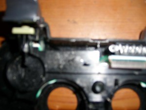
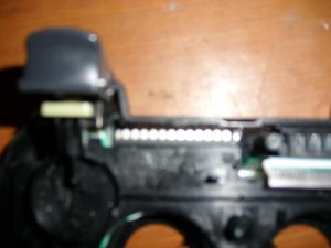
-This is the place you got the pic goes perfect, put the legs, facing away
And seeing where it goes our pic we took, we cut pieces of ide cable no more than 5 cm. And proceed to solder the points: 1,8,9,10,13,14,15,16,19,20,25,26 one for each point. Remember that the pic is looking out the points 15,16,19,20, 25 and 26 are below the pic and would have to fold them up, nothing complicated for the other points is easier as they are in the superiorNow we have to weld all the components necessary for the Pic:
2 resistance of 10 k.
1 330 ohm resistor.
1 Capacitor of 220 or 470 nf.
2 22 pf capacitors.
1 Crystal 8, 12, or 20 mhz.
1 Capacitor 100 nF.
1 LED (any color, I have not installed).
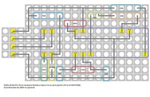
POSE follow this outline for easy interpretation
Using pieces of ide cable to connect a pic, the theme of Jumper and DC outputs, D +, D-and GRN leave enough cable about 10 cm or so to be comfortable installation whether to cut it short. The LED do not place out and I do not think it takes, now if someone wants to put it, in this photo show more or less as it should be before welding something I also can find another way to put to me was the best I found:
CLARIFICATION:
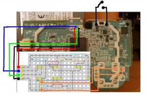
Before welding something in command must prove that pic works correctly I connect to the outputs VCC, D +, D-and GRN a USB connector and see if I tore the exploit, if all goes well we proceed to the step of welding at the helm, the points are marked with colors that are welded to the plate as is without changing anything.
See diagram that goes as everything goes online are simple welds, in the part of JUMPER must draw the two lines and put in the right stick button (THIS IS TO UPDATE THE PIC FOR FUTURE UPDATES PSGROOVE).
In the top right Note that there is an extension of the RESET button I have elongated and have added a switch that is adapted to the control unit had to use a Dremel to fit it and leave it outside (this is the most important of all for that the action cancels any usb functionality sends ushering in the Exploit). Authorities recommend any place to plug insulators between the wires, the pic and mini usb connector to ensure proper operation
Operation
*To start the Xploit just put the usb cable to the console and controller, having previously turned off and the console on the back button after having pressed the RESET button and then press the POWER button then the button to activate Eject DEBUG , wait until you leave the logo of the console, you can remove the knob and press the PS button (the middle of the panel with the initials PS, look for games and you’ll see two folders that indicate that everything went well.
*To update the PIC must have these programs installed on your PC:
-vcredist_x86.exe
-dotNetFx40_Full_setup.exe
After installing run the program:
3. HIDbootloader.exe
which is responsible for programming the pic, put the usb cable on the remote simultaneously acontinuación have tightened RESET button and left stick button (reset button is to disable any USB activity in the control and the left analog stick makes its way to activate the bootloader mode of the pic) and have fulfilled that is enough to install the other end of the usb cable to pc. The program will automatically detect the device. The same is done at the beginning of the Institute prior to installation on the remote to program. Hex of the exploit, the program’s interface is very easy to interpret.
Note: do this only when we have a new update for Pic, we must take into account that you have installed the latest updates and we can play without a disc inside (in some cases there are games that deserve it.)
Well so far all for now, I hope for something to serve this project for me has been very encouraging to have done it despite the bad reviews I’ve had thanks to all who supported me and the team of Eol.
Greetings
Continuate a seguire Informaniaci per avere tutte le novità sul mondo Playstation 3

